ทำงานกับ DAG ใน transpiler passes
ใน Qiskit ในช่วงขั้นตอนการ transpilation นั้น circuits จะถูกแทนด้วย DAG โดยทั่วไป DAG ประกอบด้วย vertices (หรือที่เรียกว่า "nodes") และ directed edges ที่เชื่อมต่อคู่ของ vertices ในทิศทางที่กำหนด การแทนนี้จัดเก็บโดยใช้ออบเจ็กต์ qiskit.dagcircuit.DAGCircuit ที่ประกอบด้วยออบเจ็กต์ DagNode แต่ละตัว ข้อดีของการแทนนี้เหนือรายการ gates ล้วนๆ (นั่นคือ netlist) คือ flow ของข้อมูลระหว่าง operations นั้นชัดเจน ทำให้ตัดสินใจในการแปลงได้ง่ายขึ้น
คู่มือนี้แสดงวิธีการทำงานกับ DAGs และนำมาใช้เขียน transpiler passes แบบกำหนดเอง โดยจะเริ่มจากการสร้าง circuit ง่ายๆ และตรวจสอบการแทน DAG จากนั้นสำรวจ operations พื้นฐานของ DAG และนำ pass BasicMapper แบบกำหนดเองมาใช้
สร้าง circuit และตรวจสอบ DAG ของมัน
โค้ดด้านล่างแสดงให้เห็น DAG โดยการสร้าง circuit ง่ายๆ ที่เตรียม Bell state และใช้การหมุน ขึ้นอยู่กับผลลัพธ์การวัด
Package versions
โค้ดในหน้านี้ถูกพัฒนาโดยใช้ requirements ต่อไปนี้ แนะนำให้ใช้เวอร์ชันเหล่านี้หรือใหม่กว่า
qiskit[all]~=2.4.0
# Added by doQumentation — required packages for this notebook
!pip install -q qiskit
from qiskit import QuantumRegister, ClassicalRegister, QuantumCircuit
from qiskit.converters import circuit_to_dag
from qiskit.visualization import circuit_drawer
from qiskit.visualization.dag_visualization import dag_drawer

# Create circuit
q = QuantumRegister(3, "q")
c = ClassicalRegister(3, "c")
circ = QuantumCircuit(q, c)
circ.h(q[0])
circ.cx(q[0], q[1])
circ.measure(q[0], c[0])

# Qiskit 2.0 uses if_test instead of c_if
with circ.if_test((c, 2)):
    circ.rz(0.5, q[1])

circuit_drawer(circ, output="mpl")

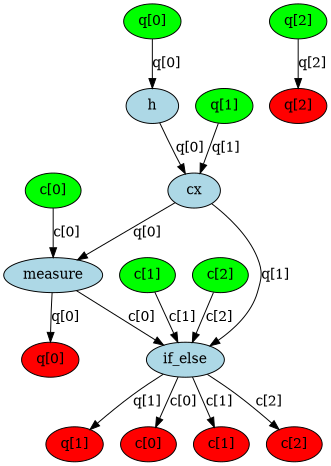
ใน DAG มี graph nodes สามประเภท ได้แก่ qubit/clbit input nodes (สีเขียว), operation nodes (สีน้ำเงิน) และ output nodes (สีแดง) แต่ละ edge แสดงการไหลของข้อมูล (หรือ dependency) ระหว่างสอง nodes ใช้ฟังก์ชัน qiskit.tools.visualization.dag_drawer() เพื่อดู DAG ของ circuit นี้ (ติดตั้ง ไลบรารี Graphviz เพื่อเรียกใช้สิ่งนี้)
# Convert to DAG
dag = circuit_to_dag(circ)
dag_drawer(dag)
Operations พื้นฐานของ DAG
ตัวอย่างโค้ดด้านล่างแสดง operations ทั่วไปกับ DAGs รวมถึงการเข้าถึง nodes การเพิ่ม operations และการแทนที่ subcircuits operations เหล่านี้เป็นรากฐานสำหรับการสร้าง transpiler passes
ดึง operation nodes ทั้งหมดใน DAG
เมธอด op_nodes() คืนค่ารายการ iterable ของออบเจ็กต์ DAGOpNode ใน circuit:
dag.op_nodes()
[DAGOpNode(op=Instruction(name='h', num_qubits=1, num_clbits=0, params=[]), qargs=(<Qubit register=(3, "q"), index=0>,), cargs=()),
 DAGOpNode(op=Instruction(name='cx', num_qubits=2, num_clbits=0, params=[]), qargs=(<Qubit register=(3, "q"), index=0>, <Qubit register=(3, "q"), index=1>), cargs=()),
 DAGOpNode(op=Instruction(name='measure', num_qubits=1, num_clbits=1, params=[]), qargs=(<Qubit register=(3, "q"), index=0>,), cargs=(<Clbit register=(3, "c"), index=0>,)),
 DAGOpNode(op=Instruction(name='if_else', num_qubits=1, num_clbits=3, params=[<qiskit.circuit.quantumcircuit.QuantumCircuit object at 0x7f1ca06de8d0>, None]), qargs=(<Qubit register=(3, "q"), index=1>,), cargs=(<Clbit register=(3, "c"), index=0>, <Clbit register=(3, "c"), index=1>, <Clbit register=(3, "c"), index=2>))]
แต่ละ node เป็น instance ของคลาส DAGOpNode:
node = dag.op_nodes()[3]
print("node name:", node.name)
print("op:", node.op)
print("qargs:", node.qargs)
print("cargs:", node.cargs)
print("condition:", node.op.condition)
node name: if_else
op: Instruction(name='if_else', num_qubits=1, num_clbits=3, params=[<qiskit.circuit.quantumcircuit.QuantumCircuit object at 0x7f1c9ee9d650>, None])
qargs: (<Qubit register=(3, "q"), index=1>,)
cargs: (<Clbit register=(3, "c"), index=0>, <Clbit register=(3, "c"), index=1>, <Clbit register=(3, "c"), index=2>)
condition: (ClassicalRegister(3, 'c'), 2)
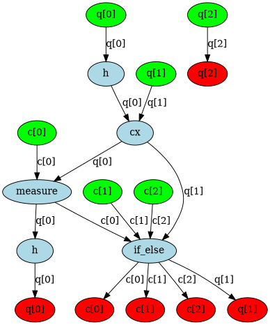
เพิ่ม operation ไปที่ท้าย
operation จะถูกเพิ่มไปที่ส่วนท้ายของ DAGCircuit โดยใช้เมธอด apply_operation_back() ซึ่งเพิ่ม gate ที่ระบุให้ทำงานบน qubits ที่กำหนดหลัง operations ที่มีอยู่ทั้งหมดใน circuit
from qiskit.circuit.library import HGate

dag.apply_operation_back(HGate(), qargs=[q[0]])
dag_drawer(dag)
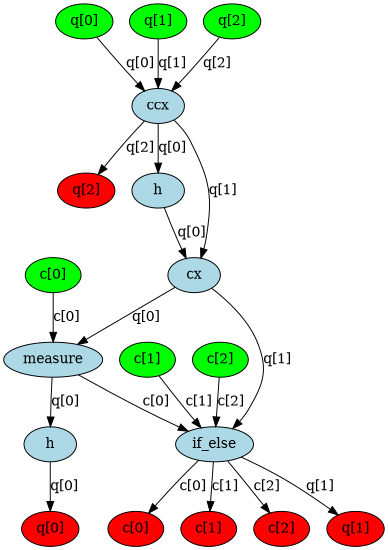
เพิ่ม Operation ไปที่ส่วนหน้า
operation จะถูกเพิ่มไปที่ส่วนเริ่มต้นของ DAGCircuit โดยใช้เมธอด apply_operation_front() ซึ่งแทรก gate ที่ระบุก่อน operations ที่มีอยู่ทั้งหมดใน circuit ทำให้มันเป็น operation แรกที่ถูกดำเนินการ
from qiskit.circuit.library import CCXGate

dag.apply_operation_front(CCXGate(), qargs=[q[0], q[1], q[2]])
dag_drawer(dag)
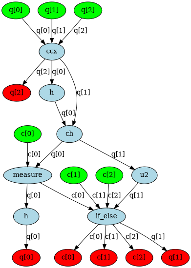
แทนที่ node ด้วย subcircuit
node ที่แทน operation เฉพาะใน DAGCircuit จะถูกแทนที่ด้วย subcircuit ขั้นแรก สร้าง sub-DAG ใหม่ที่มีลำดับ gates ที่ต้องการ จากนั้น node เป้าหมายจะถูกแทนที่ด้วย sub-DAG นี้โดยใช้ substitute_node_with_dag() โดยรักษาการเชื่อมต่อกับส่วนที่เหลือของ circuit
from qiskit.dagcircuit import DAGCircuit
from qiskit.circuit.library import CHGate, U2Gate, CXGate

# Build sub-DAG
mini_dag = DAGCircuit()
p = QuantumRegister(2, "p")
mini_dag.add_qreg(p)
mini_dag.apply_operation_back(CHGate(), qargs=[p[1], p[0]])
mini_dag.apply_operation_back(U2Gate(0.1, 0.2), qargs=[p[1]])

# Replace CX with mini_dag
cx_node = dag.op_nodes(op=CXGate).pop()
dag.substitute_node_with_dag(cx_node, mini_dag, wires=[p[0], p[1]])
dag_drawer(dag)
หลังจากการแปลงทั้งหมดเสร็จสิ้น DAG สามารถแปลงกลับเป็นออบเจ็กต์ QuantumCircuit ปกติได้ นี่คือวิธีที่ transpiler pipeline ทำงาน circuit จะถูกนำมา ประมวลผลในรูปแบบ DAG และ circuit ที่ถูกแปลงแล้วจะถูกผลิตเป็น output
from qiskit.converters import dag_to_circuit

new_circ = dag_to_circuit(dag)
circuit_drawer(new_circ, output="mpl")

นำ BasicMapper pass มาใช้
โครงสร้าง DAG สามารถนำมาใช้ประโยชน์ในการเขียน transpiler passes ในตัวอย่างด้านล่าง นำ pass BasicMapper มาใช้เพื่อ map circuit ใดๆ ลงบน device ที่มีการเชื่อมต่อ qubit แบบจำกัด สำหรับคำแนะนำเพิ่มเติม ดูคู่มือเรื่องการเขียน custom transpiler passes
pass ถูกกำหนดให้เป็น TransformationPass หมายความว่ามันแก้ไข circuit โดยทำการ traverse DAG ทีละชั้น ตรวจสอบว่า instruction แต่ละตัวเป็นไปตามข้อจำกัดที่กำหนดโดย coupling map ของ device หรือไม่ หากตรวจพบการละเมิด จะกำหนด swap path และแทรก SWAP gates ที่จำเป็นตามลำดับ
เมื่อสร้าง transpiler pass การตัดสินใจแรกคือการเลือกว่า pass ควร inherit จาก TransformationPass หรือ AnalysisPass Transformation passes ถูกออกแบบมาเพื่อแก้ไข circuit ในขณะที่ analysis passes มีจุดประสงค์เพื่อดึงข้อมูลเท่านั้นเพื่อใช้โดย passes ถัดไป ฟังก์ชันหลักจะถูก implement ในเมธอด run(dag) สุดท้าย pass ควรถูกลงทะเบียนภายในโมดูล qiskit.transpiler.passes
ใน pass เฉพาะนี้ DAG จะถูก traverse ทีละชั้น (แต่ละชั้นมี operations ที่ทำงานบนชุด qubits ที่ไม่ซ้ำกัน จึงสามารถดำเนินการได้อย่างอิสระ) สำหรับแต่ละ operation หากข้อจำกัดของ coupling map ไม่ได้รับการตอบสนอง จะระบุ swap path ที่เหมาะสม และแทรก swaps ที่จำเป็นเพื่อนำ qubits ที่เกี่ยวข้องมาอยู่ติดกัน
from qiskit.transpiler.basepasses import TransformationPass
from qiskit.transpiler import Layout
from qiskit.circuit.library import SwapGate

class BasicSwap(TransformationPass):
    def __init__(self, coupling_map, initial_layout=None):
        super().__init__()
        self.coupling_map = coupling_map
        self.initial_layout = initial_layout

    def run(self, dag):
        new_dag = DAGCircuit()
        for qreg in dag.qregs.values():
            new_dag.add_qreg(qreg)
        for creg in dag.cregs.values():
            new_dag.add_creg(creg)

        if self.initial_layout is None:
            self.initial_layout = Layout.generate_trivial_layout(
                *dag.qregs.values()
            )

        current_layout = self.initial_layout.copy()

        for layer in dag.serial_layers():
            subdag = layer["graph"]
            for gate in subdag.two_qubit_ops():
                q0, q1 = gate.qargs
                p0 = current_layout[q0]
                p1 = current_layout[q1]

                if self.coupling_map.distance(p0, p1) != 1:
                    path = self.coupling_map.shortest_undirected_path(p0, p1)
                    for i in range(len(path) - 2):
                        wire1, wire2 = path[i], path[i + 1]
                        qubit1 = current_layout[wire1]
                        qubit2 = current_layout[wire2]
                        new_dag.apply_operation_back(
                            SwapGate(), qargs=[qubit1, qubit2]
                        )
                        current_layout.swap(wire1, wire2)

            new_dag.compose(
                subdag, qubits=current_layout.reorder_bits(new_dag.qubits)
            )

        return new_dag
ตอนนี้สามารถทดสอบ pass บน circuit ตัวอย่างขนาดเล็กได้ สร้าง pass manager ที่มี pass ที่กำหนดใหม่รวมอยู่ด้วย จากนั้นให้ circuit ตัวอย่างกับ pass manager นี้ และได้รับ circuit ใหม่ที่ถูกแปลงเป็น output
from qiskit.transpiler import CouplingMap, PassManager
from qiskit import QuantumRegister, QuantumCircuit

q = QuantumRegister(7, "q")
in_circ = QuantumCircuit(q)
in_circ.h(q[0])
in_circ.cx(q[0], q[4])
in_circ.cx(q[2], q[3])
in_circ.cx(q[6], q[1])
in_circ.cx(q[5], q[0])
in_circ.rz(0.1, q[2])
in_circ.cx(q[5], q[0])

coupling = [[0, 1], [1, 2], [2, 3], [3, 4], [4, 5], [5, 6]]
coupling_map = CouplingMap(couplinglist=coupling)

pm = PassManager()
pm.append(BasicSwap(coupling_map))

out_circ = pm.run(in_circ)

in_circ.draw(output="mpl")
out_circ.draw(output="mpl")

ขั้นตอนถัดไป
- ทบทวนคู่มือเรื่องการสร้าง custom transpiler pass
- เรียนรู้วิธี สร้างและ transpile เทียบกับ custom backends
- ลองใช้คู่มือ เปรียบเทียบการตั้งค่า transpiler
- ทบทวน เอกสาร DAG Circuit API