สร้างและ Transpile กับ Custom Backend
# Added by doQumentation — required packages for this notebook
!pip install -q numpy qiskit rustworkx
# Don't use SVGs for this file because the images are too large,
# and the SVGs are much larger than their PNGs equivalents.
%config InlineBackend.figure_format='png'
```json

{/* cspell:ignore multichip interchip Lasciate ogne speranza voi ch'intrate */}
{/*
  DO NOT EDIT THIS CELL!!!
  This cell's content is generated automatically by a script. Anything you add
  here will be removed next time the notebook is run. To add new content, create
  a new cell before or after this one.
*/}

<Accordion>
<AccordionItem title="Package versions">

โค้ดในหน้านี้พัฒนาโดยใช้ requirement ต่อไปนี้
แนะนำให้ใช้เวอร์ชันเหล่านี้หรือใหม่กว่า
qiskit[all]~=2.4.0
</AccordionItem>
</Accordion>
{/* cspell:ignore LOCC */}

หนึ่งในฟีเจอร์ที่ทรงพลังที่สุดของ Qiskit คือความสามารถในการรองรับการกำหนดค่าอุปกรณ์ที่แตกต่างกัน  Qiskit ถูกออกแบบมาให้ไม่ขึ้นกับผู้ให้บริการฮาร์ดแวร์ควอนตัมที่ใช้งาน และผู้ให้บริการสามารถกำหนดค่าออบเจ็กต์ `BackendV2` ตามคุณสมบัติเฉพาะของอุปกรณ์ตัวเองได้  หัวข้อนี้จะสาธิตวิธีกำหนดค่า Backend ของตัวเองและ Transpile Circuit ควอนตัมกับ Backend เหล่านั้น

สามารถสร้างออบเจ็กต์ `BackendV2` ที่มีรูปร่างหรือ Basis Gate ต่างกัน แล้ว Transpile Circuit ด้วยการกำหนดค่าเหล่านั้นได้  ตัวอย่างด้านล่างครอบคลุม Backend ที่มี Qubit Lattice แบบไม่ต่อเนื่อง ซึ่ง Basis Gate แตกต่างกันระหว่างขอบและภายในแกนกลาง

## ทำความเข้าใจ Provider, BackendV2, และ Target Interface \{#understand-the-provider-backendv2-and-target-interfaces}

ก่อนเริ่มต้น ควรทำความเข้าใจการใช้งานและวัตถุประสงค์ของออบเจ็กต์ [`Provider`](../api/qiskit/providers), [`BackendV2`](../api/qiskit/qiskit.providers.BackendV2), และ [`Target`](../api/qiskit/qiskit.transpiler.Target)

- ถ้ามีอุปกรณ์ควอนตัมหรือ Simulator ที่ต้องการรวมเข้ากับ Qiskit SDK จำเป็นต้องเขียน class `Provider` ของตัวเอง  class นี้มีวัตถุประสงค์เดียว คือการรับออบเจ็กต์ Backend ที่กำหนดไว้  นี่คือจุดที่จัดการงานด้าน Credential และ/หรือการยืนยันตัวตนที่จำเป็น  เมื่อสร้างอินสแตนซ์แล้ว ออบเจ็กต์ Provider จะให้รายการ Backend และความสามารถในการรับ/สร้างอินสแตนซ์ Backend

- ต่อมา class Backend จะเป็นส่วนเชื่อมต่อระหว่าง Qiskit SDK กับฮาร์ดแวร์หรือ Simulator ที่ใช้รัน Circuit  ประกอบด้วยข้อมูลที่จำเป็นทั้งหมดในการอธิบาย Backend ให้กับ Transpiler เพื่อให้สามารถปรับแต่ง Circuit ตามข้อจำกัดของ Backend ได้  `BackendV2` ประกอบด้วยส่วนหลัก 4 ส่วน:
  - คุณสมบัติ [`Target`](../api/qiskit/qiskit.transpiler.Target) ซึ่งมีคำอธิบายข้อจำกัดของ Backend และให้โมเดลของ Backend สำหรับ Transpiler
  - คุณสมบัติ `max_circuits` ที่กำหนดขีดจำกัดจำนวน Circuit ที่ Backend สามารถรันได้ในงานเดียว
  - เมธอด `run()` ที่รับการส่งงาน
  - ชุด `_default_options` สำหรับกำหนดตัวเลือกที่ผู้ใช้สามารถกำหนดค่าได้และค่าเริ่มต้น

## สร้าง Custom BackendV2 \{#create-a-custom-backendv2}

ออบเจ็กต์ `BackendV2` เป็น Abstract Class ที่ใช้สำหรับออบเจ็กต์ Backend ทั้งหมดที่สร้างโดย Provider (ทั้งใน `qiskit.providers` หรือไลบรารีอื่น เช่น [`qiskit_ibm_runtime.IBMBackend`](../api/qiskit-ibm-runtime/ibm-backend))  ดังที่กล่าวไว้ข้างต้น ออบเจ็กต์เหล่านี้มีหลาย attribute รวมถึง [`Target`](https://docs.quantum.ibm.com/api/qiskit/qiskit.transpiler.Target)  `Target` มีข้อมูลที่ระบุ attribute ของ Backend เช่น [`Coupling Map`](https://docs.quantum.ibm.com/api/qiskit/qiskit.transpiler.CouplingMap), รายการ [`Instructions`](https://docs.quantum.ibm.com/api/qiskit/qiskit.circuit.Instruction), และอื่น ๆ สำหรับ Transpiler  นอกจาก `Target` แล้ว ยังสามารถกำหนดรายละเอียดระดับ Pulse เช่น [`DriveChannel`](https://docs.quantum.ibm.com/api/qiskit/1.4/qiskit.pulse.channels.DriveChannel) หรือ [`ControlChannel`](https://docs.quantum.ibm.com/api/qiskit/1.4/qiskit.pulse.channels.ControlChannel) ได้ด้วย

ตัวอย่างต่อไปนี้สาธิตการปรับแต่งนี้โดยสร้าง Backend แบบหลายชิปจำลอง ซึ่งแต่ละชิปมีการเชื่อมต่อแบบ Heavy-hex  ตัวอย่างกำหนดชุด Two-Qubit Gate ของ Backend เป็น [`CZGates`](../api/qiskit/qiskit.circuit.library.CZGate) ภายในชิปแต่ละชิป และ [`CXGates`](../api/qiskit/qiskit.circuit.library.ECRGate) ระหว่างชิป  ก่อนอื่น สร้าง `BackendV2` ของตัวเองและปรับแต่ง `Target` ด้วย Single-Qubit และ Two-Qubit Gate ตามข้อจำกัดที่กล่าวไว้

<Admonition type="tip" title="ไลบรารี graphviz">
การ Plot Coupling Map ต้องติดตั้งไลบรารี [`graphviz`](https://graphviz.org/)
</Admonition>

```python
import numpy as np
import rustworkx as rx

from qiskit.providers import BackendV2, Options
from qiskit.transpiler import Target, InstructionProperties
from qiskit.circuit.library import XGate, SXGate, RZGate, CZGate, ECRGate
from qiskit.circuit import Measure, Delay, Parameter, Reset
from qiskit import QuantumCircuit, transpile
from qiskit.visualization import plot_gate_map

class FakeLOCCBackend(BackendV2):
    """Fake multi chip backend."""

    def __init__(self, distance=3, number_of_chips=3):
        """Instantiate a new fake multi chip backend.

        Args:
            distance (int): The heavy hex code distance to use for each chips'
                coupling map. This number **must** be odd. The distance relates
                to the number of qubits by:
                :math:`n = \\frac{5d^2 - 2d - 1}{2}` where :math:`n` is the
                number of qubits and :math:`d` is the ``distance``
            number_of_chips (int): The number of chips to have in the multichip backend
                each chip will be a heavy hex graph of ``distance`` code distance.
        """
        super().__init__(name="Fake LOCC backend")
        # Create a heavy-hex graph using the
        # rustworkx library, then instantiate a new target
        self._graph = rx.generators.directed_heavy_hex_graph(
            distance, bidirectional=False
        )
        num_qubits = len(self._graph) * number_of_chips
        self._target = Target(
            "Fake multi-chip backend", num_qubits=num_qubits
        )

        # Generate instruction properties for single qubit gates and a measurement, delay,
        #  and reset operation to every qubit in the backend.
        rng = np.random.default_rng(seed=12345678942)
        rz_props = {}
        x_props = {}
        sx_props = {}
        measure_props = {}
        delay_props = {}

        # Add 1q gates. Globally use virtual rz, x, sx, and measure
        for i in range(num_qubits):
            qarg = (i,)
            rz_props[qarg] = InstructionProperties(error=0.0, duration=0.0)
            x_props[qarg] = InstructionProperties(
                error=rng.uniform(1e-6, 1e-4),
                duration=rng.uniform(1e-8, 9e-7),
            )
            sx_props[qarg] = InstructionProperties(
                error=rng.uniform(1e-6, 1e-4),
                duration=rng.uniform(1e-8, 9e-7),
            )
            measure_props[qarg] = InstructionProperties(
                error=rng.uniform(1e-3, 1e-1),
                duration=rng.uniform(1e-8, 9e-7),
            )
            delay_props[qarg] = None
        self._target.add_instruction(XGate(), x_props)
        self._target.add_instruction(SXGate(), sx_props)
        self._target.add_instruction(RZGate(Parameter("theta")), rz_props)
        self._target.add_instruction(Measure(), measure_props)
        self._target.add_instruction(Reset(), measure_props)

        self._target.add_instruction(Delay(Parameter("t")), delay_props)
        # Add chip local 2q gate which is CZ
        cz_props = {}
        for i in range(number_of_chips):
            for root_edge in self._graph.edge_list():
                offset = i * len(self._graph)
                edge = (root_edge[0] + offset, root_edge[1] + offset)
                cz_props[edge] = InstructionProperties(
                    error=rng.uniform(7e-4, 5e-3),
                    duration=rng.uniform(1e-8, 9e-7),
                )
        self._target.add_instruction(CZGate(), cz_props)

        cx_props = {}
        # Add interchip 2q gates which are ecr (effectively CX)
        # First determine which nodes to connect
        node_indices = self._graph.node_indices()
        edge_list = self._graph.edge_list()
        inter_chip_nodes = {}
        for node in node_indices:
            count = 0
            for edge in edge_list:
                if node == edge[0]:
                    count += 1
            if count == 1:
                inter_chip_nodes[node] = count
        # Create inter-chip ecr props
        cx_props = {}
        inter_chip_edges = list(inter_chip_nodes.keys())
        for i in range(1, number_of_chips):
            offset = i * len(self._graph)
            edge = (
                inter_chip_edges[1] + (len(self._graph) * (i - 1)),
                inter_chip_edges[0] + offset,
            )
            cx_props[edge] = InstructionProperties(
                error=rng.uniform(7e-4, 5e-3),
                duration=rng.uniform(1e-8, 9e-7),
            )

        self._target.add_instruction(ECRGate(), cx_props)

    @property
    def target(self):
        return self._target

    @property
    def max_circuits(self):
        return None

    @property
    def graph(self):
        return self._graph

    @classmethod
    def _default_options(cls):
        return Options(shots=1024)

    def run(self, circuit, **kwargs):
        raise NotImplementedError(
            "This backend does not contain a run method"
        )
แสดงภาพ Backend
สามารถดู Connectivity Graph ของ class ใหม่นี้ได้ด้วยเมธอด plot_gate_map() จากโมดูล qiskit.visualization เมธอดนี้ พร้อมกับ plot_coupling_map() และ plot_circuit_layout() เป็นเครื่องมือที่ช่วยในการแสดงภาพการจัดเรียง Qubit ของ Backend รวมถึงการวาง Circuit บน Qubit ของ Backend ตัวอย่างนี้สร้าง Backend ที่มีชิป Heavy-hex ขนาดเล็กสามชิป กำหนดชุดพิกัดเพื่อจัดเรียง Qubit รวมถึงชุดสีที่กำหนดเองสำหรับ Two-Qubit Gate ที่แตกต่างกัน
backend = FakeLOCCBackend(3, 3)

target = backend.target
coupling_map_backend = target.build_coupling_map()

coordinates = [
    (3, 1),
    (3, -1),
    (2, -2),
    (1, 1),
    (0, 0),
    (-1, -1),
    (-2, 2),
    (-3, 1),
    (-3, -1),
    (2, 1),
    (1, -1),
    (-1, 1),
    (-2, -1),
    (3, 0),
    (2, -1),
    (0, 1),
    (0, -1),
    (-2, 1),
    (-3, 0),
]

single_qubit_coordinates = []
total_qubit_coordinates = []

for coordinate in coordinates:
    total_qubit_coordinates.append(coordinate)

for coordinate in coordinates:
    total_qubit_coordinates.append(
        (-1 * coordinate[0] + 1, coordinate[1] + 4)
    )

for coordinate in coordinates:
    total_qubit_coordinates.append((coordinate[0], coordinate[1] + 8))

line_colors = ["#adaaab" for edge in coupling_map_backend.get_edges()]
ecr_edges = []

# Get tuples for the edges which have an ecr instruction attached
for instruction in target.instructions:
    if instruction[0].name == "ecr":
        ecr_edges.append(instruction[1])

for i, edge in enumerate(coupling_map_backend.get_edges()):
    if edge in ecr_edges:
        line_colors[i] = "#000000"
print(backend.name)
plot_gate_map(
    backend,
    plot_directed=True,
    qubit_coordinates=total_qubit_coordinates,
    line_color=line_colors,
)
Fake LOCC backend
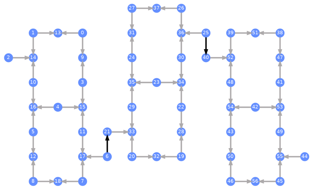
แต่ละ Qubit มีป้ายกำกับ และลูกศรสีแสดงถึง Two-Qubit Gate ลูกศรสีเทาคือ CZ Gate และลูกศรสีดำคือ CX Gate ระหว่างชิป (เชื่อมต่อ Qubit และ ) ทิศทางของลูกศรบอกทิศทางเริ่มต้นที่ Gate เหล่านี้ถูกรัน โดยระบุว่า Qubit ไหนเป็น Control/Target ตามค่าเริ่มต้นสำหรับแต่ละช่อง Two-Qubit
Transpile against custom backends
ตอนนี้เราได้กำหนด custom backend ที่มี Target เฉพาะของตัวเองแล้ว การ transpile วงจรควอนตัมกับ backend นี้ทำได้ตรงไปตรงมา เพราะข้อจำกัดที่จำเป็นทั้งหมด (basis gates, การเชื่อมต่อ Qubit และอื่นๆ) ที่ Transpiler passes ต้องการนั้นอยู่ใน attribute นี้แล้ว ตัวอย่างถัดไปสร้าง Circuit ที่สร้าง GHZ state ขนาดใหญ่ และ transpile กับ backend ที่สร้างไว้ข้างต้น
from qiskit.transpiler import generate_preset_pass_manager

num_qubits = 50
ghz = QuantumCircuit(num_qubits)
ghz.h(range(num_qubits))
ghz.cx(0, range(1, num_qubits))
op_counts = ghz.count_ops()

print("Pre-Transpilation: ")
print(f"CX gates: {op_counts['cx']}")
print(f"H gates: {op_counts['h']}")
print("\n", 30 * "#", "\n")

pm = generate_preset_pass_manager(optimization_level=3, backend=backend)
transpiled_ghz = pm.run(ghz)
op_counts = transpiled_ghz.count_ops()

print("Post-Transpilation: ")
print(f"CZ gates: {op_counts['cz']}")
print(f"ECR gates: {op_counts['ecr']}")
print(f"SX gates: {op_counts['sx']}")
print(f"RZ gates: {op_counts['rz']}")
Pre-Transpilation:
CX gates: 49
H gates: 50

 ##############################
Post-Transpilation:
CZ gates: 146
ECR gates: 6
SX gates: 302
RZ gates: 250
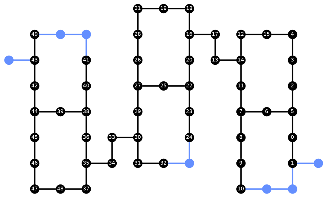
Circuit ที่ transpile แล้วตอนนี้มีทั้ง CZ และ ECR gates ผสมกัน ซึ่งเราระบุไว้เป็น basis gates ใน Target ของ backend นอกจากนี้ยังมี gates มากกว่าตอนเริ่มต้นเพราะต้องแทรก SWAP instructions หลังจากเลือก layout แล้ว ด้านล่างนี้ใช้เครื่องมือ visualization plot_circuit_layout() เพื่อระบุว่า Qubit และ two-qubit channels ไหนถูกใช้ใน Circuit นี้
from qiskit.visualization import plot_circuit_layout

plot_circuit_layout(
    transpiled_ghz, backend, qubit_coordinates=total_qubit_coordinates
)
สร้าง backends แบบไม่ซ้ำใคร
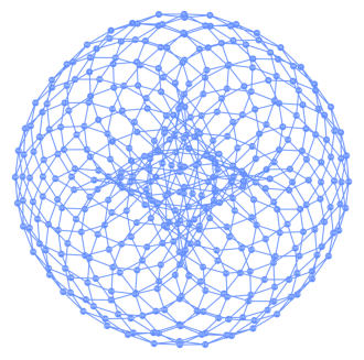
แพ็คเกจ rustworkx มีไลบรารีกราฟหลายแบบและรองรับการสร้างกราฟแบบกำหนดเอง โค้ดที่ดูน่าสนใจด้านล่างนี้สร้าง backend ที่ได้แรงบันดาลใจจาก toric code จากนั้นสามารถ visualize backend โดยใช้ฟังก์ชันจากส่วน Visualize backends
class FakeTorusBackend(BackendV2):
    """Fake multi chip backend."""

    def __init__(self):
        """Instantiate a new backend that is inspired by a toric code"""
        super().__init__(name="Fake LOCC backend")
        graph = rx.generators.directed_grid_graph(20, 20)
        for column in range(20):
            graph.add_edge(column, 19 * 20 + column, None)
        for row in range(20):
            graph.add_edge(row * 20, row * 20 + 19, None)
        num_qubits = len(graph)
        rng = np.random.default_rng(seed=12345678942)
        rz_props = {}
        x_props = {}
        sx_props = {}
        measure_props = {}
        delay_props = {}
        self._target = Target("Fake Kookaburra", num_qubits=num_qubits)
        # Add 1q gates. Globally use virtual rz, x, sx, and measure
        for i in range(num_qubits):
            qarg = (i,)
            rz_props[qarg] = InstructionProperties(error=0.0, duration=0.0)
            x_props[qarg] = InstructionProperties(
                error=rng.uniform(1e-6, 1e-4),
                duration=rng.uniform(1e-8, 9e-7),
            )
            sx_props[qarg] = InstructionProperties(
                error=rng.uniform(1e-6, 1e-4),
                duration=rng.uniform(1e-8, 9e-7),
            )
            measure_props[qarg] = InstructionProperties(
                error=rng.uniform(1e-3, 1e-1),
                duration=rng.uniform(1e-8, 9e-7),
            )
            delay_props[qarg] = None
        self._target.add_instruction(XGate(), x_props)
        self._target.add_instruction(SXGate(), sx_props)
        self._target.add_instruction(RZGate(Parameter("theta")), rz_props)
        self._target.add_instruction(Measure(), measure_props)
        self._target.add_instruction(Reset(), measure_props)
        self._target.add_instruction(Delay(Parameter("t")), delay_props)
        cz_props = {}
        for edge in graph.edge_list():
            cz_props[edge] = InstructionProperties(
                error=rng.uniform(7e-4, 5e-3),
                duration=rng.uniform(1e-8, 9e-7),
            )
        self._target.add_instruction(CZGate(), cz_props)

    @property
    def target(self):
        return self._target

    @property
    def max_circuits(self):
        return None

    @classmethod
    def _default_options(cls):
        return Options(shots=1024)

    def run(self, circuit, **kwargs):
        raise NotImplementedError("Lasciate ogne speranza, voi ch'intrate")
backend = FakeTorusBackend()
# We set `figsize` to a smaller size to make the documentation website faster
# to load. Normally, you do not need to set the argument.
plot_gate_map(backend, figsize=(4, 4))
num_qubits = int(backend.num_qubits / 2)
full_device_bv = QuantumCircuit(num_qubits, num_qubits - 1)
full_device_bv.x(num_qubits - 1)
full_device_bv.h(range(num_qubits))
full_device_bv.cx(range(num_qubits - 1), num_qubits - 1)
full_device_bv.h(range(num_qubits))
full_device_bv.measure(range(num_qubits - 1), range(num_qubits - 1))
tqc = transpile(full_device_bv, backend, optimization_level=3)
op_counts = tqc.count_ops()
print(f"CZ gates: {op_counts['cz']}")
print(f"X gates: {op_counts['x']}")
print(f"SX gates: {op_counts['sx']}")
print(f"RZ gates: {op_counts['rz']}")
CZ gates: 834
X gates: 18
SX gates: 1534
RZ gates: 1150